Components of the Simulation Engine
The following sections will explain the basic components and terminology of the BharatSim framework.
Graphs, Nodes, and Relations
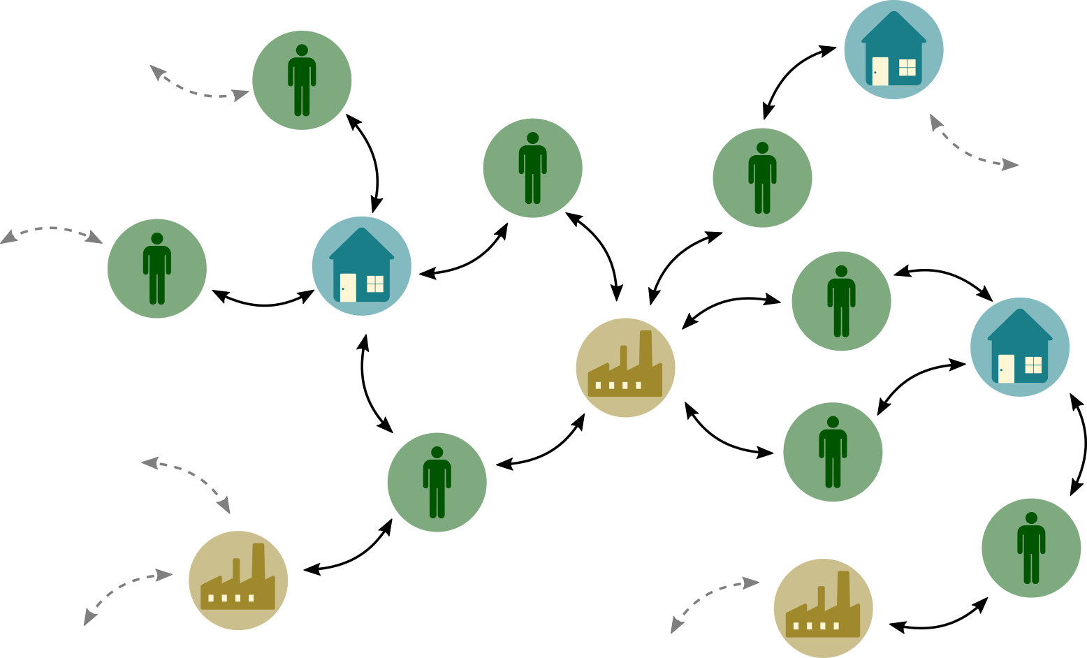
A sample Graph consisting of different nodes: people, houses, and workplaces. People are connected to their homes and workplaces through relations, and forming a contact network.
The basic data structure in which BharatSim stores its data is a Graph. This Graph is composed of multiple nodes, each specified by a unique 64-bit id. The nodes on our graph are modelled as framework-defined extensions of the Node class. Each of these instances of the Node class can be connected to every other through a Relation.
Error
Only one a single Relation may exist between two instances of a Node class. If multiple relations are defined between two Nodes, then the simulation will not know which Relation to pick, and and error will be thrown.
Agents and network locations are both modelled as extensions of the Node class, while relations are defined between them using the framework-defined addRelation() function to create an underlying network structure. The simulation engine further defines multiple functions that allow the modeler to create, access, update, and delete the nodes and their relations. We will describe them in more detail below.

A modeler can define different extensions of the Node class to represent, for example, a Person, a Home, or a Work location.
Agents and Behaviours
In agent-based modelling, a system generally consists of a group of automata that make decisions at every time-step, based on data from each other and the environment. These automata are called “agents”. In BharatSim, agents can be modelled using the framework-defined Agent class, which is an extension of the Node class. To allow for heterogeneity present in real-world individuals, different instances of the Agent class can possess different user-defined attributes, like their age, occupation, vaccination status, and so on. Multiple classes of agents can be defined in a single simulation. Every class of agent will have to be registered using the framework-defined registerAgent() function.
At each time step, an Agent is allowed to execute an action, known as a behaviour. This is implemented in BharatSim through a framework-defined addBehaviour() function that every Agent posesses, which can be used to define a custom behaviour that is executed at every time step.
These behaviours allow the agents in our simulation to mimic the actions of real individuals in a population. For example, in the case of disease-modelling, one might use a behaviour to decide if an unvaccinated agent will get vaccinated on a specific day, based on the result of a daily coin-toss.
Depending on the level of heterogeneity introduced in the population by the modeller, these behaviours can be modelled as close to real-world actions as possible.
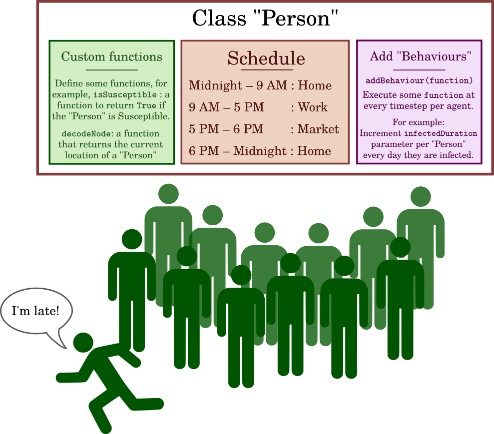
Representation of the Agent class: agents can be made to execute actions at every time-step through the addBehaviour function, but can also have custom functions that can be called. The agent’s movement between different network locations is governed by a “schedule” (described below).
Networks
The Network class is another framework-defined extension of the Node class which can be used to model physical locations or contact-networks in a simulation.
In addition to the standard functions that the Node class provides, the Network class has a getContactProbability function which allows the programmer to model differential disease transmission based on network locations. For example, a crowded public-transport location might lead to a much higher probability of transmission of an infectious disease, when compared to an open office with very few employees.
The Network class can be extended by the modeller to describe different network locations, such as homes, workplaces, and schools, for example. Each network location is linked to a class of agent using a different relation, specified by the addRelation function. In this case, the nodes would be the Agent and the specific extension of the Network class.
Note
The addRelation function establishes a relation between any two nodes, not just Agent and Network classes. It is possible to have two agents that have a relation between them, and similarly it is possible to have two network locations that have a relation between them. For an example of the latter, see Houses on a lattice.

Illustration of bidirectional relationships between classes of nodes.
To illustrate the point, consider a simple model in which we define three types of network locations: a Home, a Work location, and a School. Every agent in the population is assigned one of these, with multiple agents being assigned the same home, workplace, and school, based on data from the synthetic population. Each agent is connected to each location using user-defined relations. For example, we could say that a Person IS_EMPLOYED_BY a specific Work location, and that the Work location EMPLOYS the Person. Thus, the relations IS_EMPLOYED_BY and EMPLOYS connect the Person and Work classes.
Every Agent has a Home with a unique id, and therefore a contact network associated with their family – i.e., the other agents who have been assigned the same Home. Similarly, this agent and all other agents who share the same workplace id are assumed to work together, forming a professional network. Agents can be made to spend different amount of times with these different network locations based on their schedules, which can lead to complex social dynamics.
Schedules
In order to account for the movement of individuals between different network locations, the BharatSim framework implements a “schedule” which specifies for how long an Agent is linked to a specific Network location. These schedules allow the modeller to decide what fraction of a unit of time (say, a day of 24 hours) the agent spends in each location. Each agent is assumed to follow this schedule, and this allows them to move between network locations over time, governed by their Schedule.
Different agents can be given different schedules, based on their attributes or other factors. For example, if we define all individuals under the age of 18 to be schoolchildren and all those above the age of 18 to be working adults, we could assign all children to schools and all adults to workplaces, and give them different schedules based on this distinction. Taking another example, a modeller could assign agents an attribute is_employed which is set to true if the agent is employed. We could then define different schedules, an “employed” schedule and an “unemployed” schedule, requiring agents to follow the appropriate schedule based on their employment status. The condition for assigning an Agent a specific schedule can thus be made as general or specific as required.
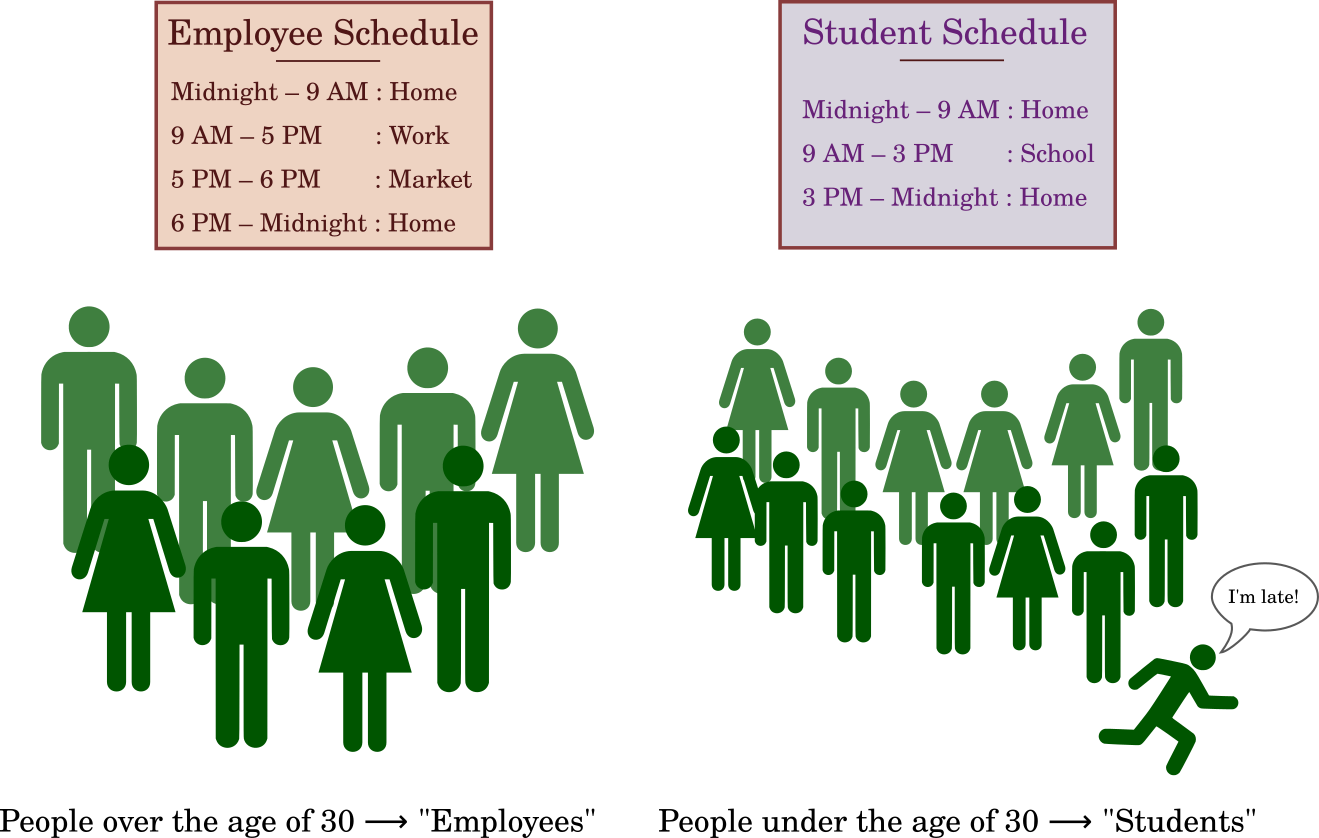
Different types of Persons can have their own schedule based on age, jobs, and socio-economic status.
Furthermore, the same agent can be assigned multiple schedules. Which schedule the agent follows at any given simulation tick is dictated by a “priority” parameter that is set when the schedule is defined. With all else being the same, the schedule with the higher priority is given precedence.
Finite State Machine
A Finite State Machine is a class of algorithms where an abstract machine can be in exactly one of the finite state at any given time. A “state” is defined as the explicit trait of the system and this can be changed after satisfying a said boolean condition. This change from one state to another state is called a transition, and the criteria for a transition between two different pair of states may vary based on modeller choices. This is best illustrated through an example of traffic lights.
Current State |
Next State |
Condition |
|---|---|---|
Green |
Yellow |
120 seconds |
Yellow |
Red |
20 seconds |
Red |
Green |
120 seconds |
The above table lists the “state” the system can be in and the possible transition condition that needs to be satisfied. Suppose the system just entered the Green state, then this implies that are after spending 120 seconds being Green, the system will transition to the Yellow state.
BharatSim possesses a framework-defined Finite State Machine which allows users to define a State as an extension of the Scala programming language’s trait datatype. Every distinct state in the model can be created as user-defined extensions of the State trait. These user-defined extensions can further allow for transitions between different states using the framework-defined addTransition function that every State` possesses.
Every type of State should be registered in the Simulation using the framework-defined registerState function.
Stateful Agent
In order to make use of the Finite State Machine, BharatSim defines an extension of the Agent class called the StatefulAgent class. Such agents possess an activeState which links them to one – and only one – instance of a State trait. Additionally, a StatefulAgent also possesses two important functions:
setInitialState: which sets the initial state of aStatefulAgent, andfetchActiveState: which returns the current state of theStatefulAgent.
Like agents, a StatefulAgent also needs to be registered in the Simulation using the registerAgent function.
Actions
Additionally, in BharatSim, the State trait also posses certain “actions” that are executed by every StatefulAgent associated with that State, based on certain conditions:
An
enterActionis an action aStatefulAgentexecutes the moment they transition into aStatefor the first time.A
perTickAction: is an action executed by aStatefulAgenton every day that they are associated with thatState, very much like a behaviour.
Transitions
Additionally, similar to how agents have an addBehaviour function,the State trait allows for an addTransition function that can be used to check at every time-step if each StatefulAgent associated with that State is allowed to transition to another state.